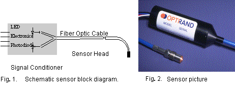
associated with
optical connectors the signal conditioner (“smart” connector) is permanently
attached to the sensor cable. Fig. 2 shows
a photograph of a typical sensor.
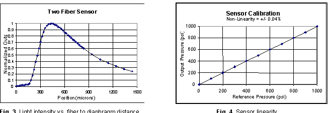
The sensor response to pressure results
from the displacement of a diaphragm that in turn changes optical signal
transmitted from the sending to the receiving fiber upon reflection from the
diaphragm. Over a large displacement range light intensity collected by the
receiving fiber may either decrease or increase with increasing diaphragm to
fiber distance, as shown in Fig.3. In
a pressure sensor, the diaphragm displacement is quite small, typically around
20 microns. For a given diaphragm
diameter, shape, and thickness, and therefore full scale deflection at maximum
pressure, the sensor response (e.g. light modulation, nominal signal level, and
linearity) can be significantly changed by changing the fiber core and cladding
sizes, Numerical Aperture, separation between fibers, and fiber to diaphragm
distance at zero pressure [6]. Fig. 4
demonstrates an experimental sensor response at constant temperature compared to
a research grade reference transducer. Note excellent response linearity
exceeding typical values of many laboratory devices.
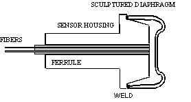
The diaphragm is one of the most
critical sensor elements. In a low-cost and durable design, Optrand sensor’s
diaphragm is made of a nickel-based alloy and is shaped during the coining
process. The diaphragm is laser welded to a metal housing containing a fiber
holding ferrule and two fibers bonded inside the ferrule, as schematically
shown in Fig. 5. Please note that
the dimensions shown in Fig. 5 are
not to scale.
Fig. 5. Sensor head
design
At present the diaphragm diameters range from 1.7mm to 8 mm covering the pressure range from 7 bar (100psi) to 2000 bar (30,000psi). Small diaphragm diameters create a significant design challenge due to the simultaneous requirement of large deflection (for high signal to noise ratio) and low stresses required for infinite lifetime. In some natural gas compressor applications the sensor has to function reliably over billions of pressure cycles. The diaphragm reflectivity must also remain nearly unchanged over the sensor lifetime. To ensure durable operation, the present sensor uses an Optrand patented sculptured, hat-shape diaphragm with varying thickness across its diameter [6]. A high strength alloy (Inconel) has been used as a diaphragm material. This material and design have been selected so that the peak stresses of the diaphragm are below the level guaranteeing an infinite lifetime. Other benefits of the present construction include excellent linearity of the pressure response and reduced sensitivity to direct flame and hot combustion gas effects.
The opto-electronic
conditioner contains low-cost and reliable PIN Si photodiode and near infrared
LED and a small in size all analog electronic circuitry. Two input electrical
leads are for power supply and ground while one output pin is for pressure
output and the other for sensor fault diagnostics. The electronic circuitry
controls light intensity, amplifies and filters photodiode signal, and provides
the auto referencing function. This Optrand patented technique regulates LED
light intensity in response to any undesirable environmental conditions that
may alter minimum detected light intensity [6]. Baseline light intensity in
fiber optic sensors may vary due to optical link transmission fluctuations
resulting from connector mechanical and thermal instabilities, fiber bending,
light source or detector temperature dependence, or aging over time. The
auto-referencing approach not only corrects for offset drift but sensor gain
error as well. A side benefit of the technique, not possible with other
combustion pressure sensors, is the availability of sensor health monitoring
output. By continuously monitoring the LED current level or its rate of change,
one can identify potential sensor failure before it occurs. This ability is
particularly important in control applications where sensor failure may cause
malfunction or even failure of the controlled device.
SENSOR
PACKAGES: Covering a wide range
of applications, Optrand offers sensor packages that can accommodate different
sizes and shapes, mounting techniques and locations. In particular, due to
their miniature sizes and high temperature and EMI resistance, Optrand sensors
can be uniquely fitted into pressure sensing spark plugs, glow plugs, or fuel
injectors. Such multifunctional devices allow non-invasive combustion cylinder
pressure detection without need for engine head drilling or modifications. For
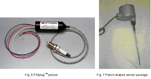
spark ignited engines Optrand offers sensors mounted in a modified production
spark plug, the PSIplug, as shown in Fig.
6. For reciprocating engines and compressors two types of mountings are
typically used in the industry, one in which the sensor is installed inside the
cylinder head and the other when an indicator valve is employed. Mounting of a
dynamic pressure sensor in the cylinder head is preferred resulting in
high-pressure data fidelity (lack of channel resonances), accuracy (reduced
thermal transients due to head water-cooling), and sensor durability (reduced
sensor temperature). For such application Optrand offers pencil shaped packages
as small as 5mm in diameter and as long as 30 centimeters. For applications
where EMI/RFI is not a concern, the signal conditioner may be attached to the end
of a pencil-like shaft, as shown in Fig.
7. For safety, the sensor signal conditioner may be mounted inside an
explosion proof enclosure. A package like this is already in use to monitor and
control large reciprocating compressors.
Another important parameter that is monitored in various types of engines is fuel pressure. For this application Optrand offers stand-alone sensors as well sensors integrated with fuel injectors [7]. Such a “smart” injector, called PSIjetTM, can be fitted in addition with a combustion cylinder pressure sensor, for optimum performance, reliability, and low-cost. The resulting device does not need to be individually balanced, as currently done, so its price can be significantly lower. Differences caused by manufacturing variability, aging, pressure line fluctuations, or fuel quality can be compensated for by using a closed-loop control of fuel timing, duration, and pressure.
SENSOR SPECIFICATIONS AND
PERFORMANCE: The basic
specifications of the pressure sensors currently offered by Optrand for control
and monitoring applications of industrial engines and machinery are summarized
below:
|
Pressure
range: |
0-7
bar (100psi) through 0-2,000 bar
(30,000psi) |
|
Overpressure |
x2,
x1.5 of pressure range |
|
Continuous sensor
temperature range: |
-40
to 300oC (570oF) |
|
Intermittent sensor
temperature range: |
Combustion |
|
-40
to 200oC (390oF) |
|
|
-40
to 65oC (150oF); model AutoPSI–S –40
to 125oC (260 oF); model AutoPSI–HT |
|
|
Frequency
response: |
0.01
Hz to 30 kHz (models AutoPSI–S, AutoPSI-TC) 0
Hz to 5kHz (model AutoPSI–DC) |
|
Linearity
& hysteresis – non-combustion |
+/-0.25 to
+/-0.5% Full Scale Output |
|
Linearity
& hysteresis – combustion |
+/-1
to +/-2% Full Scale Output |
|
Temperature
coefficient of sensitivity: |
+0.03%/
oC (model AutoPSI–S) +/-
0.005%/ oC (model AutoPSI–TC) |
|
Signal
to Noise Ratio |
2000:1
@ 15 kHz |
|
Sensor
output: |
0.5-5
V |
|
Sensor
diagnostics output |
0
– 3.6V |
|
Guaranteed
service life time |
500
Million cycles, 3 years (indicator valve mounted) 1
billion cycles, 5 years (head mounted) |
Below
we present the series of sensor performance data obtained in various monitoring
and control applications including passenger cars, natural gas engines and
compressors, and marine diesel engines.
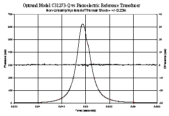
Fig. 8 demonstrates the comparison data obtained with a miniature
Optrand sensor in a single cylinder diesel engine (Yanmar). A water-cooled,
head-mounted research-grade piezoelectric transducer (Kistler 6061) was used as
a reference.
Fig
8. Single cylinder diesel engine test data comparison between AutoPSI-S sensor
and piezoelectric reference transducer
The data presented in
Fig. 8 were obtained with a sensor
designed for nominal 3000-psi (200 bar) pressure range. The left side vertical
axis is for both optical and reference transducers while the right side axis
shows the difference between the sensor readings. The measurement and reference
traces are normalized so their peak-to-peak values are equalized. Compared to
the full-scale output of approximately 650psi, +/-0.23% accuracy was recorded,
including linearity, hysteresis, repeatability, and thermal shock.
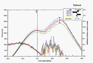
The data obtained on
a large-bore natural gas engine is shown in Fig.9 comparing the performance of Optrand sensor against an
air-cooled strain gauge transducer (Enspec). Both sensors were mounted in a
Kiene valve, external to the engine head. Fig.
4. Note excellent linearity, hysteresis, and thermal shock performance of
+/-1% of Optrand uncooled sensor.
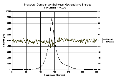
Fig. 9. Engine test comparison between Optrand and reference
sensors on a natural gas engine
Fig. 10 shows the data obtained on a large, high-speed (1,500-RPM)
compressor. The sensor package used in this application is shown in Fig. 7. The sensor was mounted inside
an existing indicator channel with the diaphragm flush mounted with the
compressor cylinder wall. Please note an excellent fidelity of pressure data
free of periodic perturbations associated with sensors mounted at the end of an
indication channel.
Fig. 10. Pencil-like sensor performance in a compressor
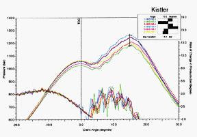
Finally, Fig. 11 demonstrates a comparison between Optrand and Kistler
sensors performance in a diesel engine of a naval ship. Both sensors were
installed in a Kiene valve of the engine
indicator port.
Fig. 11 Optrand vs. Kistler sensor (Model 7613) comparison
on a naval ship engine
During the last 12 months several hundred sensors have been subjected to endurance and calibration stability tests in natural gas and diesel engines as well as gas compressors and fuel injection pumps. With the exception of some sensors that were damaged by incorrect handling and a few defective sensors, all the sensors have demonstrated durability exceeding 500 Million pressure cycles or 12,000 hours. In compressor and fuel injection endurance tests the sensors have already demonstrated over 1 Billion pressure cycles service lifetime and target 3-5 Billion cycles.
In addition to the endurance tests, during the last year tens of sensors have been subjected to long-term calibration stability tests. Periodically, every few to several months, Optrand sensors were re-calibrated using air or water-cooled reference transducers (strain gauges or piezoelectric sensors). During a 6 to 12 month period the sensors demonstrated excellent calibration stability (compared to the initial values), ranging from a non-detectable to +/-0.1% change in the sensor sensitivity value.
SUMMARY AND CONCLUSIONS:
In a robust, durable, and low-cost design Optrand fiber optic pressure sensors
operate on the principle of light reflection from a metal diaphragm flexing
under the effect of pressure. When optimized for high linearity, optical signal
level, and modulation, the sensor demonstrates accuracy comparable to that of a
laboratory-grade piezoelectric transducer. For combustion engine applications
the sensor as small as 1.7 mm in diameter can be either directly inserted into
an engine head or integrated with a spark plug, glow plug, or fuel injector. At
constant temperature the sensor accuracy is typically +/- 0.25%; under
combustion conditions the combined sensor’s hysteresis, non-linearity, and
thermal shock effects result in pressure reading accuracy of +/-1% to +/-2%
full-scale output. Currently Optrand offers four types of sensors: AutoPSI-S,
AutoPSI-TC, AutoPSI-HT, and AutoPSI-DC. The originally developed “-S” sensor
provides the most economical solution for dynamic pressure measurement. The
AutoPSI-TC sensor offers temperature-compensated operation matching the
performance of water-cooled piezoelectric sensors without water or air-cooling
and at fraction of cost. The AutoPSI-HT sensor comes with a signal conditioner
rated for –40°C to 125°C. Finally, the AutoPSI-DC sensor offers the capability
of continuous static pressure detection at 300°C. Currently the AutoPSI-S and
AutoPSI-HT sensors are guaranteed for 500-Million pressure cycles or three
years under combustion engine conditions and for indicator valve mounting. For
head-mounted combustion applications the warranty is extended to unprecedented
1 Billion pressure cycles. In compressor or fuel injection applications,
currently the sensor service lifetime is guaranteed for 1 Billion cycles and it
is expected shortly to increase to 3 billions. To date, hundreds of Kiene valve
mounted sensors have demonstrated the lifetime of at least 12,000 hours and
over 500 Million pressure cycles. The sensors have also demonstrated an
excellent calibration stability, better that 0.1% over a 6 month period,
respectively.
REFERENCES:
[1]. “Optical Fiber Sensors: Systems and Applications”, Ed. B. Culshaw & J. Dankin, Artech House, 1989.
[2]. J.W. Berthold
and S.E. Reed, “Flight test results from FOCSI fiber optic total pressure
transducer,” Proc. SPIE, Vol. 2072, 1993.
[3]. M. Lequime and
C. Lecot, “Fiber optic pressure and temperature sensor for down-hole
applications,” Proc. SPIE, Vol. 1511, 1991.
[4]. Chung E. Lee, et
al., "In-Line Fiber Fabry-Perot Interferometer with High-Reflectance
Internal Mirrors," Journal of
Lightwave Technology, vol. 10, No. 10,
Oct., 1992, pp. 1376-1379.
[5]. J. Rouhet, P.
Graindorge, L. Laloux, M. Girault, P. Martin, H.C. Lefevre, F.X. Desforges,
“Application of Fiber Optic Sensors to Cryogenic Spacecraft Engines”, SPIE vol.
3000, pp.29-36, 1997.
[6].
M. T. Wlodarczyk “Fiber-Optic Combustion Pressure Sensor for Automotive Engine
Controls,” SPIE Vol.3000, Laser Diode and LED Applications III, San Jose,
California, 10-11 February 1997.
[7]. T. Poorman,
Liangdao Xia, and M. T. Wlodarczyk “Ignition System-Embedded Fiber-Optic
Combustion Pressure Sensor for Automotive Engine Control and Monitoring,” SAE
Paper No. 970853, 1997.