
Long-Life Fiber-Optic Pressure Sensors for Monitoring and Control of Gas Machinery
Tom Poorman, Jacob Arnold, Terry Coleman, and Marek T. Wlodarczyk
Optrand, Inc.
Plymouth, Michigan
ABSTRACT
In a robust, durable, and low-cost design Optrand pressure sensors utilize the principle of light intensity changes, transmitted by two optical fibers, upon reflection from a specially shaped, metal diaphragm deflecting under the effect of pressure. The non-contact detection principle combined with the diaphragm design optimized for infinite fatigue life translates into a sensor with extraordinary lifetime. The sensor’s signal conditioner contains one LED and one photodiode and is permanently attached to the fibers. The electronic circuitry provides the auto-referencing function compensating for the effects of fiber bending, fiber-to-optoelectronics coupling changes, sensor thermal drift, as well as temperature and aging effects of the LED and the photodiode. The results of several long-term tests in two key gas machinery applications are reported here: continuous and intermittent monitoring of power and compressor cylinders. In the longest application to date, hundreds of combustion pressure sensors have demonstrated over 12,000 hours or 500-Million pressure-cycle lifetime. Dynamic pressure sensors for compressor monitoring have already demonstrated the lifetime of 1 billion cycles and target 5 billions. In compressor applications the sensor demonstrates typical +/-0.25% accuracy while combustion pressure sensor accuracy is typically +/-1%. For almost two years tens of indicator valve-mounted combustion sensors have been monitored for calibration stability demonstrating better than +/-0.1% performance over a 6-month period.
1. INTRODUCTION
Over the last ten years the gas machinery industry has seen an explosive growth in the use of automation technology. Through a fusion of computer hardware and software, data acquisition systems, and sensors and actuators, automation provides a platform for implementing advanced control and monitoring that can measurably reduce emission levels and improve productivity and reliability of reciprocating and turbine engines and compressors. Advancements in automation have provided technology that requires significantly less expertise and manpower to maintain system integrity and reliability. Technology advancements in the area of PC-based data acquisition have provided for standard, off-the-shelf products that provide the necessary data acquisition rates and computing power. Network and remote communication advancements allow for monitoring, diagnosis and analysis of machinery information from virtually anywhere. Finally, advancements in wireless communications resulted in the capability to transmit and receive data using radio frequency [1].
One of the most critical components of the gas machinery automation is a system that monitors key system parameters and functions. In the rotating engines and compressors of natural gas pumping stations such a parameter is cylinder pressure. Engine and compressor cylinder pressure can be related to horsepower and emission levels (through Parametric Emission Monitoring Systems), efficiency, throughput, and leak status and qualification [2]. In addition, cylinder pressure evolution over time is the indication of machinery health providing diagnostics and prognostics information and enabling Condition Based Maintenance [3]. When incorporated into an "adaptive" control scheme, continuous pressure monitoring can provide continuous optimization of emissions, efficiency, reliability and range of operability.
The lack of reliable, long-life and cost-effective pressure sensors has been the main reason control and monitoring systems have found little use so far in reciprocating gas engines and compressors. Electronic sensors that dominate the pressure measurement field can not meet the durability and reliability specifications for continuous monitoring that may require service lifetime of 1 billion cycles or more. Historically, piezoelectric transducers have been used in high-temperature cylinder applications (typically up to 200-250° C for quartz devices and 125-150° C for piezo-ceramics). While special natural-quartz devices may operate up to 350°C without water cooling, they have limited durability and are prohibitively expensive. Piezo-ceramics can be cost effective but are limited to low temperatures and not durable due to transfer pins or contacting elements. Developed over the last ten years, Silicon micro-machined sensors offer potential for very low cost by adapting some of the batch manufacturing processes from the VLSI industry. Benefiting from engine block water or air-cooling and mounting location, Silicon-based transducers have been even proposed for combustion cylinder pressure measurement. However, due to fundamental temperature limitation of Silicon (150°C) and EMI/RFI susceptibility, these sensors are not suitable for operation without cooling or in harsh environments. Higher-temperature rated transducers and electronic components based on the Silicon Carbide (SiC) semiconductor material have been under development for the last 20 years aimed at operation at temperatures as high as 500°C. In the area of combustion pressure detection, some functional SiC sensors have been recently reported by the teams lead by Daimler Benz in Europe [4] and NASA in the U.S. While short-term operation was demonstrated, performance and long-term reliability remain a major concern due to detrimental effects of lead oxidation, alloy phase segregation, and diffusion. These devices also suffer from the same EMI/RFI susceptibility as any other electronic devices. Finally, highly specialized and expensive manufacturing processes make SiC sensors very expensive, even in large volumes.
For gas machinery applications fiber optic pressure sensors (FOPS) have been identified as the best solution for monitoring and control use [5]. They offer inherent advantages over electronic devices including non-electrical nature, resistance to high temperature and chemical attack, and potential for long service lifetime. By separating a high-temperature fiber-optic transducer from its opto-electronic and electronic signal conditioner, FOPS may operate continuously at temperatures up to 400°C or more in the transducer area and may have lifetime of tens of thousands of hours. The fiber optic sections of these sensors are intrinsically safe and free of EMI and RFI, permitting very long sensor cables and use in explosive media. Due to exceptional sensitivity the sensors can be very small (of the order of millimeter) offering a possibility of integration with other, higher functionality devices. Finally, FOPS may be resistant to corrosive and chemically aggressive environments.
Unfortunately, to date fiber sensors have not fulfilled their promise for widespread use due to a combination of technical, practical, and cost limitations. From the technical standpoint, the majority of reported FOPS are typically convoluted in the signal conditioner area due to the use of bulky, fragile, and dissimilar optical components and materials such as fused fiber optic couplers, electro-optic modulators, and component receptacles [6]-[9]. Many fiber optic sensors, such as those based on the interferometric principle, use laser diodes, single mode fibers, waveguide modulators, or ferrite isolators. Typically the sensing fiber connects to its signal conditioner via an optical connector leading to high cost and performance limitations associated with fiber optic connectors. Sensor designs that do not use optical connectors are either limited in their temperature ratings to 70°C, due to the use of laser diodes or other photonic devices, or are bulky and not robust due to the use of discrete opto-electronic components. From the cost standpoint, fiber-optic sensors suffer from high component and manufacturing costs, typically one to two orders of magnitude more than their electronic counterparts. While some of these cost disadvantages are related to lower production volumes, it is primarily the construction, materials, components, and fabrication techniques of present-day FOPS that make these devices very expensive.
Optrand has developed a family of fiber optic sensors that specifically target monitoring and control use under harsh operating conditions and alleviate the limitation of other FOPS. The sensors emphasize robustness, long life, and low cost. This paper describes the sensor operating principle, design, packaging and mounting issues, and performance in gas machinery applications including power and compressor cylinders
2.OPTRAND SENSOR DESCRIPTION
As shown in Fig. 1, the fiber optic sensor
developed by Optrand consists of three basic components: a
sensing head with a metal diaphragm directly exposed to
combustion pressure, a cable containing two multimode fibers, and
an opto-electronic signal conditioner containing all optical and
electronic components. To avoid the "real-world"
problems associated with optical connectors the signal
conditioner ("smart" connector) is permanently attached
to the sensor cable. Fig. 2 shows a photograph of a
typical sensor.

Fig. 1. Schematic sensor
block diagram.
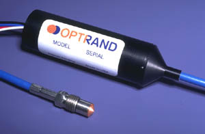
Fig. 2. Sensor picture
The sensor response to pressure results from the displacement of a diaphragm that in turn changes optical signal transmitted from the sending to the receiving fiber upon reflection from the diaphragm. In a two-fiber design, light intensity collected by the receiving fiber may either decrease or increase with increasing diaphragm deflection. For a given diaphragm displacement due to a full scale pressure change the sensor response can be adjusted by a suitable choice of optical fiber core diameters and numerical apertures, as well as relative position of the fibers in respect to the diaphragm [10].
In a robust and durable design the sensor head consists of a metal housing with a welded sensing diaphragm, a fiber holding ferrule, and two fibers bonded inside the ferrule, as schematically shown in Fig. 3. Please note that the dimensions shown in Fig. 3 are not to scale.

Fig. 3. Sensor head design
The diaphragm is one of the most critical elements of the sensor. At present its diameter ranges from 1.7mm to 8 mm covering the pressure range from 100psi to 30,000psi. Small diaphragm diameters create a significant design challenge due to the simultaneous requirement of large deflection (for high signal to noise ratio) and low stresses required for infinite lifetime. In a typical natural gas compressor application the sensor has to function reliably over billions of pressure cycles. The diaphragm reflectivity must also remain nearly unchanged over the sensor lifetime. To ensure durable operation, the present sensor uses an Optrand patented sculptured, hat-shape diaphragm with varying thickness across its diameter. A high strength alloy (Inconel) has been used as a diaphragm material. This material and design have been selected so that the peak stresses of the diaphragm are below the level guaranteeing an infinite lifetime. Other benefits of the present construction include excellent linearity of the pressure response and reduced sensitivity to direct flame and hot combustion gas effects.
The opto-electronic conditioner contains low-cost and reliable PIN Si photodiode and near infrared LED, and a small in size all analog electronic circuitry. Two input electrical leads are for power supply and ground while one output pin is for pressure output and the other for sensor fault diagnostics. The electronic circuitry controls light intensity, amplifies and filters photodiode signal, and provides the auto referencing function. This Optrand patented technique regulates LED light intensity in response to any undesirable environmental conditions that may alter minimum detected light intensity [10]. Baseline light intensity in fiber optic sensors may vary due to optical link transmission fluctuations resulting from connector mechanical and thermal instabilities, fiber bending, light source or detector temperature dependence, or aging over time. The auto-referencing approach not only corrects for offset drift but sensor gain error as well. A side benefit of the technique, not possible with other combustion pressure sensors, is the availability of sensor health monitoring output. By continuously monitoring the LED current level or its rate of change, one can identify potential sensor failure before it occurs. This ability is particularly important in control applications where sensor failure may cause malfunction or even failure of the controlled device.
3. SENSOR PACKAGES AND MOUNTING
Depending on an application, Optrand offers a wide range of sensor
packages to accommodate different mounting techniques and locations. For reciprocating
gas engines and compressors two types of mountings are typically used in the
industry, one in which the sensor is installed inside the cylinder head and
the other when an indicator valve is employed. Mounting of a dynamic pressure
sensor in the cylinder head is preferred resulting in high-pressure data fidelity
(lack of channel resonances), accuracy (reduced thermal transients due to head
water-cooling), and sensor durability (reduced sensor temperature). However,
the gas machinery industry has historically used indicator cocks and vales,
despite their problems including overheating, channel resonances, and soot deposits.
In such approaches a special valve is installed into the engine head connected
to the combustion or compressor cylinder via an indicator passage, as shown
in Fig.4.
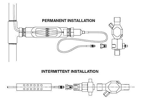
Fig. 4. Indicator valve sensor mounting techniques
For permanently mounted sensors the indicator valve is modified compared to the presently used intermittent applications to accommodate a sensor and a shut off plunger. The sensor is mounted into a special bolt-like adapter that provides protection against port detonation and reduces thermal effects associated with hot combustion gasses. The sensor signal conditioner is typically mounted inside compression fitting of an explosion proof metal conduit.
For head-mounted applications, or mounting inside an indicator
channel, Optrand offers unique pencil-like packages with diameters as small
as 5mm and lengths up to several inches. By adjusting the pencil length, the
sensing diaphragm can be positioned flush with the cylinder deck, eliminating
any channel resonances and other problems mentioned above. An installation technique
for a pencil-like sensor is shown in Fig. 5.
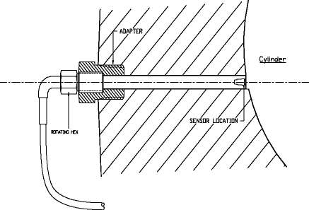
Fig. 5. Example of a head mounted sensor
For applications where EMI/RFI is not a concern, the signal conditioner
may be attached to the end of a pencil-like shaft, as shown in Fig. 6.
For safety, the sensor signal conditioner may be mounted inside an explosion
proof enclosure. A package like this is already in use to monitor and control
large reciprocating compressors.
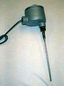
Fig. 6. Indicator channel-mounted sensor package for compressor monitoring
4. SENOR PERFORMANCE
The basic specifications of the pressure sensors currently offered by Optrand for control and monitoring applications of gas machinery are summarized below:
| Pressure range: | 0-100bar (1500psi), 0-350bar (5000psi) |
| Overpressure | x4 or x2 of pressure range |
| Continuous sensor temperature range: | -40 to 300°C(570°F) |
| Intermittent sensor temperature range: | combustion |
| Cable temperature | -40 to 200°C (390°F) |
| Signal conditioner temperature: | -40 to 65°C (150°F);
model AutoPSI–S –40 to 125°C (260°F); model AutoPSI–HT |
| Frequency response: | 0.01 Hz to 30
kHz (models AutoPSI–S, AutoPSI-TC) 0 Hz to 5kHz (model AutoPSI–DC) |
| Linearity & hysteresis – non-combustion | +/-0.25 to +/-0.5% Full Scale Output |
| Linearity & hysteresis – combustion | +/-1 to +/-2% Full Scale Output |
| Temperature coefficient of sensitivity: | +0.03%/ °C
(model AutoPSI–S) +/- 0.005%/ °C (model AutoPSI–TC) |
| Signal to Noise Ratio | 2000:1 @ 15 kHz |
| Sensor output: | 0.5-5 V |
| Sensor diagnostics output | 0 – 3.6V |
| Guaranteed service life time | 500 Million cycles, 3 years
(indicator valve mounted) 1 billion cycles, 5 years (head mounted) |
Below we present the series of sensor performance data obtained in laboratory tests as well as natural gas reciprocating engines and compressors, including long term endurance and calibration stability data.
Figure 7 demonstrates the laboratory comparison data obtained with a miniature Optrand sensor in a diesel engine. A water-cooled, head-mounted research-grade piezoelectric transducer (Kistler Model 6061) was used as a reference.

Fig 7. Single cylinder diesel engine test data comparison between AutoPSI-S sensor and piezoelectric reference transducer (Kistler Model 6061).
The data presented in Fig. 7 were obtained with a sensor designed for nominal 1,500-psi pressure range. The left side vertical axis is for both optical and reference transducers while the right side axis shows the difference between the sensor readings. The measurement and reference traces are normalized so their peak-to-peak values are equalized. Compared to the full-scale output of approximately 650psi, +/-0.52 accuracy was recorded, including linearity, hysteresis, repeatability, and thermal shock.
The data obtained on a large-bore natural gas engine is shown in Fig. 8 comparing the performance of Optrand sensor against an air-cooled strain gauge transducer (Enspec). Both sensors were mounted in a Kiene valve, similarly to what is shown in Fig. 4. Note excellent linearity, hysteresis, and thermal shock performance of +/-1% of Optrand uncooled sensor.
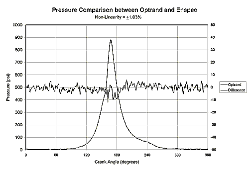
Fig. 8. Engine test data comparison between Optrand and reference sensors on a large-bore natural gas engine
Figure 9 shows the data obtained on a large, high-speed (1,500-RPM) compressor. The sensor package used in this application is shown in Fig. 6. The sensor was mounted inside an existing indicator channel with the diaphragm flush mounted with the compressor cylinder wall. Please not an excellent fidelity of pressure data free of periodic perturbations associated with sensors mounted at the end of an indication channel.
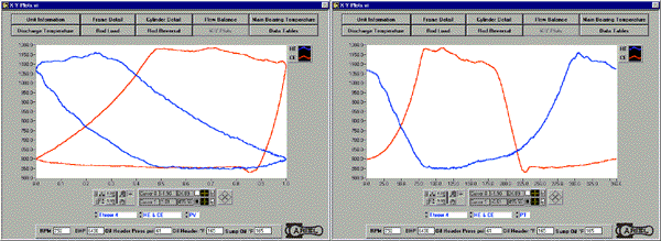
Fig. 9. Pencil-like sensor performance in a compressor
During the last 12 months several hundred sensors have been subjected to endurance and calibration stability tests. Most of the sensors were mounted in the Kiene indicator valves. With the exception of some sensors that were damaged by incorrect handling and a few defective sensors, all the sensors have demonstrated durability exceeding now 12,000 hours. The results of one long-tern engine test are shown in Fig. 10. The test involved a large-bore and small moving (350-RPM) engine of a compressor station. Fig. 10 demonstrates the performance obtained after approximately 100 Million pressure cycles. The reference sensor was Kistler sensor model 6121, intermittently mounted on the engine. For clarity the traces were shifted horizontally.

Fig. 10. Pressure response comparison between Optrand sensor and a piezoelectric reference transducer after 100 Million pressure cycles
In addition to the endurance tests, during the last year tens of sensors have been subjected to long-term calibration stability tests. Periodically, every few to several months, Optrand sensors were re-calibrated using air or water-cooled reference transducers (strain gauges or piezoelectric sensors). During a 6 to 12 month period the sensors demonstrated excellent calibration stability (compared to the initial values), ranging from a non-detectable to +/-0.1% change in the sensor sensitivity value.
5.SUMMARY AND CONCLUSIONS
Optrand has developed and offers commercially fiber-optic pressure sensors for long-term control and monitoring under harsh operating conditions. In a robust, durable, and low-cost design these sensors operate on the principle of light reflection from a metal diaphragm flexing under the effect of pressure. The optoelectronic components used in the sensors include low cost near-infrared LED and SI PIN photodiode. To combat the LED intensity and photodiode sensitivity changes over a temperature range of -40oC to 125oC, and other factors that may affect the fiber optic link transmission such as connector instability or fiber bending, a proprietary auto-referencing technique is used. The sensor optoelectronic and electronic components are packaged inside a miniature "smart" connector that outputs the pressure and sensor-health signals. When optimized for high linearity, optical signal level, and modulation, the sensor demonstrates accuracy comparable to that of a laboratory-grade piezoelectric transducer. At constant temperature the sensor accuracy is typically +/- 0.25%; under combustion conditions the combined sensor’s hysteresis, non-linearity, and thermal shock effects result in pressure reading accuracy of +/-1% to +/-2% full-scale output. For gas machinery applications Optrand offers four types of sensors: AutoPSI-S, AutoPSI-TC, AutoPSI-HT, and AutoPSI-DC. The originally developed "-S" sensor provides the most economical solution for dynamic pressure measurement. The AutoPSI-TC sensor offers temperature-compensated operation matching the performance of water-cooled piezoelectric sensors without water or air-cooling and at fraction of cost. The AutoPSI-HT sensor comes with a signal conditioner rated for –40°C to 125°C. Finally, the AutoPSI-DC sensor offers the capability of continuous static pressure detection at 300°C. Currently the AutoPSI-S and AutoPSI-HT sensors are guaranteed for 500-Million pressure cycles or three years under combustion engine conditions and for indicator valve mounting. For head-mounted combustion applications the warranty is extended to unprecedented 1 Billion pressure cycles. In compressor applications, currently the sensor service lifetime is guaranteed for 1 Billion cycles and it is expected shortly to increase to 3 billions. To date, hundreds of Kiene valve mounted sensors have demonstrated the lifetime of at least 12,000 hours and over 500 Million pressure cycles. The sensors have also demonstrated an excellent calibration stability, better that 0.1% over a 6 month period.
6. REFERENCES
[1]. R. McKee, "Continuous Compressor Performance Monitoring: Leveraging Current Technology for Optimal Benefits", 1998 GMRC Conference, Denver, October 1998.
[2]. S. Clowney, G. Beshouri, "Evaluation of Simple Peak Pressure Based Emission Models for Application to Reciprocating IC Engines in Gas Pipeline Transmission Service," 1997 GMRC Conference, Denver, October 1996.
[3]. R. Caccese and K. Albright, "A Common Sense Approach to Condition Based Maintenance for U.S. Navy Fleet Diesel Engines", Proceedings of the American Society of Naval Engineers Condition-Based Maintenance Symposium, Arlington, VA 1998
[4]. R. Ziermann, J. von Berg, W. Reichert, E. Obermeier, " A High Temperature Pressure Sensor Width ß-SiC-Piezoresistors on SOI-Substrates," Transducers 97, Chicago, Illinois, USA, June 16 - 19, 1997, Digest of Technical Papers, 1411 – 1414.
[5]. G. Beshouri, "Application of Fiber Optic Pressure Sensors to On Line Engine and Compressor Monitoring," 1998 GMRC Conference, Denver, October 1998.
[6]. J.W. Berthold and S.E. Reed, "Flight test results from FOCSI fiber optic total pressure transducer," Proc. SPIE, Vol. 2072, 1993.
[7]. M. Lequime and C. Lecot, "Fiber optic pressure and temperature sensor for down-hole applications," Proc. SPIE, Vol. 1511, 1991.
[8]. Chung E. Lee, et al., "In-Line Fiber Fabry-Perot Interferometer with High-Reflectance Internal Mirrors," Journal of Lightwave Technology, vol. 10, No. 10, Oct., 1992, pp. 1376-1379.
[9]. J. Rouhet, P. Graindorge, L. Laloux, M. Girault, P. Martin, H.C. Lefevre, F.X. Desforges, "Application of Fiber Optic Sensors to Cryogenic Spacecraft Engines", SPIE vol. 3000, pp.29-36, 1997.
[10]. M. T. Wlodarczyk "Fiber-Optic Combustion Pressure Sensor for Automotive Engine Controls," SPIE Vol.3000, Laser Diode and LED Applications III, San Jose, California, 10-11 February 1997.