Fiber-Optic Pressure Sensors for Harsh Environment Applications
Marek T. Wlodarczyk, Ph.D.
President and CEO
OPTRAND Inc.
Plymouth, Michigan 48170
ABSTRACT
Optrand has developed and offers commercially a family of long-life, miniature fiber-optic pressure sensors for use in harsh environments characterized by extreme temperatures (from –40oC to 360oC), high levels of Electromagnetic and Radio Interference, and in the presence of violate chemical materials. In a durable and low-cost design the sensor detects changing light reflection from a specially shaped metal diaphragm under the effect of pressure. Sensors as small as 2.8mm in diameter are available covering pressure ranges from 0-100 psi to 0-30,000 psi.
Two types of sensors are available, FiberPSI and AutoPSI. The FiberPSI sensor uses a single fiber while multiple fibers are used in the AutoPSI sensor. The opto-electronic components of the sensors' signal conditioners include one surface emitting LED and one or two SI PIN photodiodes. To combat LED intensity and photodiode sensitivity changes due to ambient temperature fluctuations, a proprietary auto-referencing technique has been developed that does not require temperature regulation of the optoelectronic package. The referencing technique compensates for other phenomena as well, that can alter baseline light intensity, such as fiber bending, connector mechanical and thermal instabilities, or fiber transmission changes due to radiation or temperature effects.
The FiberPSI sensor opto-electronic and electronic components are located inside a separate signal conditioner mounted in a rugged metal enclosure (5'x7'x2'). The sensor connects to the conditioner via an optical connector. The AutoPSI conditioner is packaged inside a small, "smart" connector permanently attached to the sensor fiber optic cable. In both FiberPSI and AutoPSI cases, the signal conditioners output pressure and sensor-health signals. When optimized for high linearity and reduced thermal effects, over the sensor tip temperature from –40oC to 350oC the AutoPSI sensor demonstrates as low as
-/+0.25% FSO accuracy while typical accuracy of the FiberPSI system is at +/-0.5% FSO.
The FiberPSI and AutoPSI sensors offer dynamic pressure detection capability over the frequency range of 0.01 Hz to 15kHz, with a possibility to 100kHz. Present sensor applications include R&D and testing of internal combustion engines as well as long-term monitoring of diesel and natural gas engines. Over two-year continuous use, the sensors have demonstrated over 600-Million pressure-cycle lifetime in stationary natural gas-burning engines. Currently the sensors are guaranteed for 500 Million cycles of lifetime. More than one hundred sensors are already installed to continuously monitor and balance large-bore stationary engines used in natural gas pumping stations. In it first OEM application, in 1998 the AutoPSI-S sensor will be used to control and monitor natural gas-fueled electricity-generating engines.
A recently developed AutoPSI-TC sensor offers temperature-compensated dynamic pressure capability. Using Optrand's proprietary technique, changes in the sensor diaphragm's deflection with temperature are compensated by changing the optical transmission of the fiber. As a result, the AutoPSI-TC matches the performance of water-cooled piezoelectric sensors without water or air-cooling and at fraction of cost. While the signal conditioner of the AutoPSI-TC sensor is currently rated for –40oC to 65oC, a version for –40oC to 125oC will be offered in early 1998.
Finally, the AutoPSI-DC sensor is the newest addition to the AutoPSI family. The sensor offers world's only capability of continuous static pressure detection at 360oC. In addition to pressure the sensor measures temperature by an electric sensor embedded within the sensor package. Over the sensor tip temperature range of –40oC to 350oC the device currently offers +/-1% FSO pressure and temperature reading accuracy.
1. INTRODUCTION
Fiber-optic sensors offer unique benefits in harsh environment applications characterized by very high temperatures, high levels of electromagnetic interference (EMI), chemical attack, or in the presence of explosive materials [1]. They can be of very small size and located hundreds of meters from a measurement site. An example of an extreme environment application where an optical fiber sensor may be the only solution for a reliable and durable measurement device is pressure measurement of a combustion engine cylinder. In-cylinder mounted pressure sensors may be subjected to combustion gas temperatures as high as 1,500oC and pressures up to 15,000 psi. For monitoring and control applications the sensor has to function reliably over hundreds of Millions of pressure cycles. Finally, for automotive applications the sensor has to cost less than $10 before it can be considered for use in production engines.
It is the lack of reliable, long-life and cost-effective pressure sensors that has hampered the implementations of control and monitoring systems in reciprocating and turbine engines based on combustion pressure information. Conventional pressure transducers, such as piezoresistive or piezoelectric, are not suited for long-term high temperature pressure measurements. Fundamentally, strain or capacitance gages used in pressure transducers exhibit large non-repeatable and unpredictable changes in gauge output at temperatures typically greater than 125oC or 250oC, respectively. These changes are caused by such effects as alloy segregation, phase changes, selective oxidation, and diffusion, and ultimately lead to premature failure of the gauge or lead wires.
The majority of fiber optic sensors described in the literature and potentially suitable for harsh environment applications encountered in aeronautic applications are generally not robust enough and too expensive for commercial applications [2]-[4]. In particular the vast majority of interferometric sensors that offered potential for highly sensitive and accuracy have not fulfilled these promises due to inherent problems related to practicality, stability, performance, packaging robustness, and high cost.
The most successful fiber optic pressure sensor to date that targets harsh environment applications is an interferometric sensor utilizing a low finesse Fabry-Perot cavity attached to the tip of a multimode fiber [5]. The associated signal conditioner uses a spectrometer to monitor the change of the sensing element reflectivity, under the effect of applied pressure. The sensor connects to its signal conditioner via an optical connector. While useful for laboratory use, the sensor system is, however, not robust enough and cost effective for large-scale commercial applications.
Two types of robust and low-cost fiber optic sensor systems are described in this paper, FiberPSI and AutoPSI. The FiberPSI sensor uses a single fiber vs. multiple fibers used in the AutoPSI design. The transducer consists of a metal diaphragm and a fiber or fibers located behind the diaphragm in a hermetic metal package. In an amplitude-modulated approach, applied pressure causes light intensity changes upon reflection the flexing diaphragm. As shown in Fig. 1a the FiberPSI sensor system consists of a transducer located at the distal end of a rugged fiber optic cable and a separate opto-electronic interface/signal conditioner. The conditioner unit contains four key components: LED/photodiode pair, 2x1fused coupler, all analog electronic circuitry, and optical in-line connector. An optional power supply can be used as well. The sensor cable is terminated with an optical connector interfacing to the conditioner through a receptacle mounted in the conditioner enclosure.

Figure 1a. FiberPSI sensor system block diagram.
A key component of the signal conditioner, the transceiver, contains a 2x1 fused fiber optic coupler, a GaAlAs LED emitting at 850 nm, and a Silicon PIN photodiode. An optical fiber used in the coupler is matched to the sensor fiber and typically has Numerical Aperture (NA) of 0.28 and core diameter of 62.5 microns. No heating elements are used in the transceiver to maintain the LED/photodiode package temperature at constant temperature. Instead, the circuitry relies on our patented auto-referencing technique, as described below, to compensate for any potential errors arising from the temperature dependence of LED intensity and photodiode sensitivity, as well as other environmental or handling conditions.
Unlike the FiberPSI sensor, the AutoPSI does not require any separate signal conditioners. By eliminating the fused coupler in the AutoPSI design, the physical size of the conditioner is so small that it can be fitted in a "smart" connector permanently attached to the fiber cable, as schematically shown in Fig. 1b. The current connector size is 3'' long and 1'' in diameter. By replacing the presently used Surface Mount Electronics with a custom Application Specific Integrated Circuit (ASIC) the smart connector may be as small as an electrical connector used in automotive applications.

Figure 1b. AutoPSI sensor system block diagram.
The auto referencing technique performed by the sensor electronics is applicable to both types of sensors: single fiber-based FiberPSI and multiple-fiber AutoPSI. The circuitry, schematically shown in Fig. 2, is used for dynamic pressure measurements and is intended to compensate for errors that may otherwise result from optical link instabilities due to connectors' mechanical and thermal susceptibility, fiber bending, or light source or detector temperature dependence. In a "smart" way the sensor's input parameter, LED light intensity is adjusted in response to environmental conditions so the minimum detected light intensity is always maintained at a constant level. This not only corrects for any possible offset drift but also for the sensor gain errors. A side benefit of the auto-referencing technique, not available to other combustion pressure sensors, is the availability of sensor health monitoring output in our system. By continuously monitoring the LED current level or its rate of change, one can identify potential sensor failure before it occurs. This ability is particularly important in control applications where sensor failure may cause malfunction or even failure of the controlled device.

Figure 2. Auto-referencing circuitry schematic diagram.
Unlike in testing and R&D, a pressure sensor intended for engine monitoring and control applications does not need to be extremely accurate. The critical features are high reliability, low cost, and long life. The basic specifications of the pressure sensors currently offered by Optrand for control and monitoring applications are summarized below:
|
Pressure range: |
0 - 100, 0-1000,0-3000,0-12000, 0-30000 psi |
|
Sensor temperature range: |
-40 to 360 oC |
|
Signal conditioner temperature: |
-40 to 125 oC |
|
Frequency response: |
0 Hz to 15kHz |
|
Linearity & hysteresis @ constant temperature: |
+/-0.25 to +/-0.5% |
|
Output: |
0.5-5 V |
|
Guaranteed life time |
500 Million cycles or 2 years |
The AutoPSI and FiberPSI sensors share the same sensor head construction. The head consists of three basic elements: 1) Diaphragm, 2) Sensor housing, and 3) Ferrule. In the case of FiberPSI sensor only a single fiber is used, as depicted in Fig. 2a.

Figure 2a. FiberPSI sensor head construction.
The AutoPSI sensor had, as schematically shown in Fig. 2b, has identical external dimensions but uses two or more fibers, typically of different core size and numerical aperture compared to those used in the FiberPSI.

Figure 2b. AutoPSI sensor head construction.
The sensing diaphragm is the most critical element of the sensor. It must maintain excellent mechanical properties at extreme operating conditions and function repeatably over hundreds of millions of pressure cycles. Its reflectivity must also remain nearly unchanged over the sensor lifetime. To ensure durable and accurate operation, the present sensor uses a hat-shape diaphragm with varying thickness across its diameter. A high strength alloy (Inconel) has been used as a diaphragm material. This proprietary diaphragm design has been selected so it can meet fatigue life of 1 Billion cycles and the overpressure requirement. Other benefits of the present construction include excellent linearity of the pressure response and reduced sensitivity to direct flame effects. In addition, the diaphragm is welded to sensor housing away from the flexing area, thus improving long term weld stability and strength. A high-temperature fused-silica optical fiber is bonded inside a metal ferrule to form a hermetic joint between the metal and the fiber surfaces. The ferrule tip location in respect to the diaphragm is a critical parameter and varies depending on the sensor design. An optimum location is required to accomplish required linearity of response as well as desired optical signal and modulation depth.
The modeling and analysis of the sensor have been broken down into two basic categories: (1) optical modulation and non-linearity analysis including the effect of fiber diameter, numerical aperture, and relative position in respect to the diaphragm, and (2) mechanical modeling including diaphragm deflection calculations, finite element stress analysis, and fatigue life time calculations.
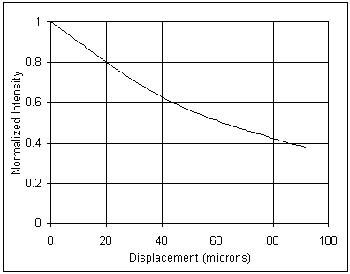
The sensor response to pressure results from the displacement of a diaphragm that in turn results in changes in an optical signal collected either by an optical fiber. The same fiber is used in the FiberPSI design for both light delivery and collection. Two or more fibers are used in the AutoPSI sensor with one or more fibers directly connected to a light source and the other fibers attached to the light detectors. For a given diaphragm displacement, resulting from a pressure change, the sensor response can be adjusted by a suitable choice of optical fiber's core diameter and numerical aperture. Fig. 3 shows how detected optical signal depends on the fiber to diaphragm separation for the FiberPSI sensor. Note that the response is monotonic and quite linear for displacements of the order of 10-20 microns that the diaphragm is subjected to.

Figure 3a. Normalized light intensity change as a function of fiber to diaphragm distance, single-fiber design.
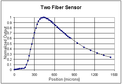
In comparison, the response of the AutoPSI sensor, as shown in Fig. 3b, is non-monotonic over a large range of distances. The region corresponding to closer diaphragm to fiber distance is typically more sensitive to diaphragm displacement and therefore is preferred for pressure sensor applications.

Figure 3b. Normalized light intensity change as a function of fiber to diaphragm distance, two-fiber design.
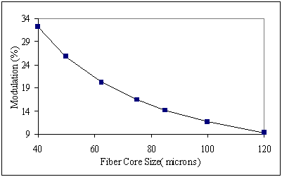
For a given diaphragm diameter, shape, and thickness, and therefore full scale deflection due to maximum pressure, the sensor response can be significantly changed by changing the fiber core and cladding sizes, NA, separation between fibers (AutoPSI sensor), and fiber to diaphragm distance at zero pressure. Figure 4a demonstrates how optical modulation, defined as a percentage of returned signal at full scale deflection to a signal at zero deflection, can be increased by approximately a factor of two by reducing the fiber core size from 100 to 62.5 microns, in the case of FiberPSI sensor.

Figure 4a. Calculated optical modulation versus fiber core diameter, FiberPSI sensor
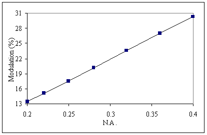
Similarly Figs. 4b shows how a significant modulation increase can be obtained by increasing fiber numerical aperture from 0.22 to 0.37, for FiberPSI sensor.

Figure 4b. Maximum light modulation as a function of fiber numerical aperture, single-fiber design.
When optimized, both FiberPSI and AutoPSI sensors provide similar degree of linearity and optical modulation. In the case of FiberPSI the total light level is typically greater due to a lower signal loss for one- versus multiple-fiber design. A theoretical pressure response of the sensor is shown in Fig. 5.

Figure 5. Calculated optical modulation versus applied pressure.
The main objective of the mechanical part of the sensor analysis focuses on the diaphragm design that results in maximum deflection under full pressure change and minimum levels of Von Misses stresses. Several high strength metal and non-metal materials were considered that could possibly satisfy the above primary design criteria. Inconel 718 alloy was finally selected primarily due to its excellent high temperature strength, low creep, and good deflection characteristics. A hat-shaped diaphragm design was identified as superior compared to the previously reported [6] flat disk diaphragm. In an optimized hat-shape design, varying diaphragm thickness can significantly reduce the maximum stress levels. In effect, the diaphragm becomes thicker and stronger were maximum stress occurs in a flat disk. Similarly, the thickness of the hat-shaped diaphragm is reduced and stresses increased in the areas of low stresses in a flat disk. The result is that up to 50% reduction in stresses is possible in a hat shaped versus flat disk diagram designs. With low stress levels and a particular type of Inconel 718 material and heat treatment specifications, the fatigue lifetime of 1 billion cycles should be possible for the present diaphragm design.
Laboratory testing of the fiber optic sensor includes linearity and hysteresis comparisons against commercially available piezoelectric sensors, temperature soaking and cycling, and sensitivity dependence on temperature. Fig. 6 demonstrates a comparison of the typical room temperature dynamic pressure responses, over 0 to 1000 psi pressure range, of the OPTRAND's AutoPSI-S sensor and a reference piezoelectric transducer (PZT) (Kistler Model 6121).

Figure 6. Dynamic pressure comparison between Optrand AutoPSI sensor and a piezoelectric transducer
Note excellent linearity exceeding typical values of many laboratory devices. The signal to noise ratio (SNR) of approximately 2000-3000 is comparable to that a reference transducer.
In a series of engine tests the performance of an engine head- and spark plug-mounted fiber optic pressure sensors was compared to that of a piezoelectric reference transducer water-cooled and directly mounted in the engine head [7]. Fig. 7 demonstrates the results obtained with a miniature Optrand sensor in a single cylinder, gasoline- fueled electricity-generating engine. A water-cooled, head-mounted research-grade piezoelectric transducer (made by Kistler) was used as a reference.

Figure 7. Engine test data comparison between AutoPSI-S sensor and piezoelectric reference on a gasoline engine
The data presented in Fig. 7 were obtained with a sensor designed for nominal 1,000-psi pressure. The left side vertical axis is for both optical and reference transducers while the right side axis shows the difference between the sensor readings. The measurement and reference traces are normalized so their peak-to-peak values are equalized. Compared to the full-scale output of approximately 250 psi, +/-0.44% accuracy was obtained, comparable to the best performance of water-cooled sensors.
The data obtained on a diesel engine is shown in Fig. 8 comparing again the performance of Optrand sensor against a water-cooled piezoelectric transducer. Note an excellent performance, below +-0.25% FSO error, under combustion conditions.

Figure 8. Engine test data comparison between AutoPSI-S sensor and piezoelectric reference on a diesel engine
The results of a 2 year long engine test are shown in Fig. 9. The test involved a large-bore and small moving (350 RPM) engine used in natural gas pipe line compressor stations. Fig. 9 demonstrates the performance obtained after approximately 200 Million pressure cycles.

Figure 9. Pressure response comparison between Optrand sensor and a piezoelectric reference transducer after 200 Million pressure cycles
It is to be noted that the piezoelectric sensor trace in Figs. 9 shows considerably more noise, especially near pressure peaks. This effect is due to the fact that approximately 30-ft long cables were used to connect the sensors to their respective signal conditioning units. While the fiber optic sensor is essentially insensitive to the cable length, the piezoelectric sensor signal is considerably reduced and therefore susceptible to ignition noise appearing near the peak pressure.
Optrand has developed and offers commercially fiber-optic pressure sensors intended for long-term control and monitoring applications under harsh operating conditions. In a robust and low-cost design these sensors operate on the principle of light reflection from a metal diaphragm flexing under the effect of pressure. Two types of sensors are available: the FiberPSI that utilizes a single fiber and the AutoPSI sensor, which is based on a multiple-fiber construction. The optoelectronic components used in the sensors include a single LED and one or two SI PIN photodiodes. To combat LED intensity and photodiode sensitivity changes over a temperature range of -40oC to 125oC, and other factors that may affect the fiber optic link transmission such as connector instability or fiber bending, a proprietary auto-referencing technique is used. For combustion engine applications the sensor, as small as 2.8 mm in diameter, can be either directly inserted into an engine head or integrated with a spark plug, glow plug, or fuel injector. The sensor optoelectronic and electronic components are packaged inside a miniature "smart" connector that outputs the pressure and sensor-health signals. When optimized for high linearity, optical signal level, and modulation, the sensor demonstrates accuracy comparable to that of a laboratory-grade piezoelectric transducer. At constant temperature the sensor accuracy can be as good as +/- 0.05%; under engine operating conditions the combined sensor's hysteresis, non-linearity, and thermal shock effects result in pressure reading accuracy of +/-0.5% to +/-1% full scale output. Currently the sensor is guaranteed for 500-Million pressure cycles or two years of lifetime under combustion engine conditions, with the lifetime expected to increase to 1 Billion cycles or 10 years inn the near future. To date, the sensor has demonstrated the lifetime of approximately 600 Million pressure cycles over a two and a half-year evaluation period. Approximately one hundred of sensors are already in use for continuos monitoring and balancing of large-bore, stationary engines used in gas pumping stations. The first OEM application will start in natural gas-fueled electricity generating engines in 1998.
[1]. "Optical Fiber Sensors: Systems and Applications", Ed. B. Culshaw & J. Dankin, Artech House, 1989.
[2]. J.W. Berthold and S.E. Reed, "Flight test results from FOCSI fiber optic total pressure transducer," Proc. SPIE, Vol. 2072, 1993.
[3]. M. Lequime and C. Lecot, "Fiber optic pressure and temperature sensor for down-hole applications," Proc. SPIE, Vol. 1511, 1991.
[4]. Chung E. Lee, et al., "In-Line Fiber Fabry-Perot Interferometer with High-Reflectance Internal Mirrors," Journal of
Lightwave Technology, vol. 10, No. 10, Oct., 1992, pp. 1376-1379.
[5]. J. Rouhet, P. Graindorge, L. Laloux, M. Girault, P. Martin, H.C. Lefevre, F.X. Desforges, "Application of Fiber Optic Sensors to Cryogenic Spacecraft Engines", SPIE vol. 3000, pp.29-36, 1997.
[6]. G. He, A. Patania, M. Kluzner, D. Vokovich, V. Astrakhan, T. Wall, and M. Wlodarczyk, "Low-cost spark plug-integrated fiber optic sensor for combustion pressure monitoring," SAE paper no. 930853, presented at SAE International Congress and Exposition, Detroit, MI, March, 1993.
[7]. T. Poorman, Liangdao Xia, and M. T. Wlodarczyk "Ignition System-Embedded Fiber-Optic Combustion Pressure Sensor for Automotive Engine Control and Monitoring," SAE Paper No. 970853, 1997.